kf8kk.com

John Martins'
Amateur Radio from near Empire Michigan USA


Other Useful Pages:

W8TVC.COM

IOOK.ORG

Rubber Ducks

VHF Propagation


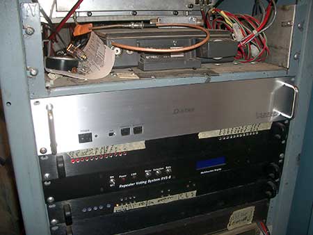
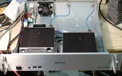
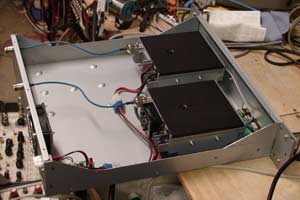
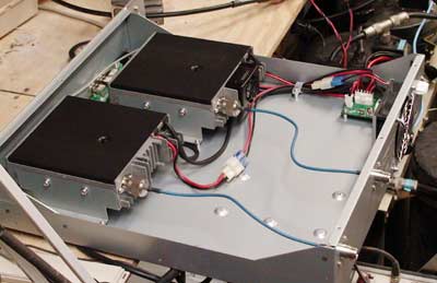
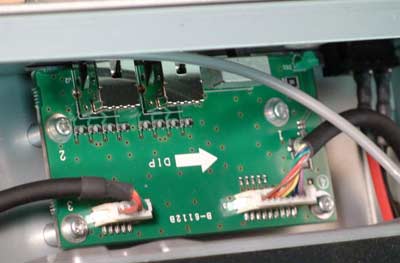
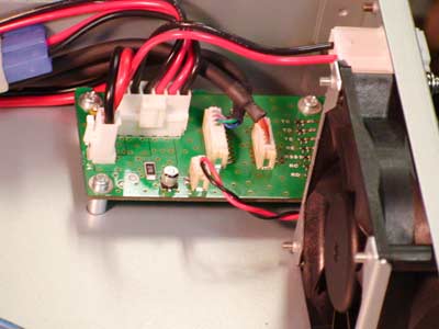
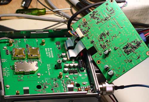
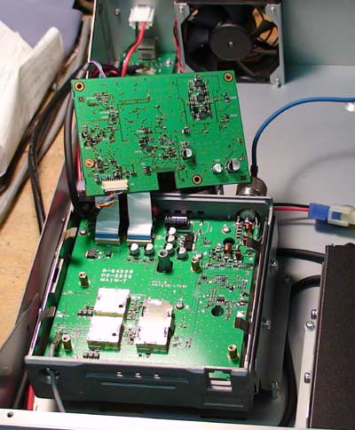
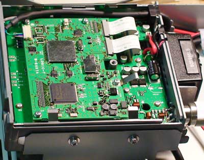
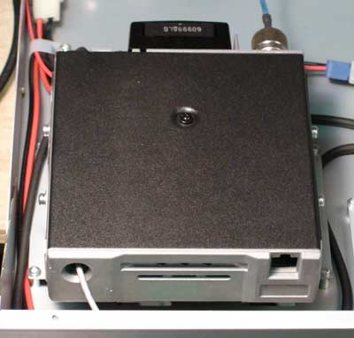
The two meter RF portion of a DStar repeater system is the RP2000V.

As any curious geek would do, I could not help myself but to pop open the case and take a look at what's inside. I include the photos of my unit below.

Something that you must understand about the DStar repeaters is that no place in the system are regular analog audio, cos or ptt brought out for interfacing to external devices. The DStar repeater controller module gets a digital feed from the RF shelves and there is no provision for any analog interface.

If you had plans to save a buck and use your old ACC RC850 on your DStar repeater you have a choice of giving up that notion, or spending a large amount of time inventing your own interface.

By the way, for those thinking of saving a few bucks and using two mobiles 'back to back' for your repeater (with an analog controller in between) please reconsider that notion.

The AMBE codec which is a core part of DStar is a very lossy codec. With one pass through the encoder and decoder you retain fairly good intelligibility but already can notice a distinctly digital sound to the audio (much like cellphone audio). If you run the audio through this encoding/decoding a second time you will find that what comes out is not just awful-- but bad...er, BAD (capitalized on purpose!-- that's BAD BAD!). Think of the normal audio path (one pass through the AMBE codec) as if you made a lousy photocopy of an original document. Think of a second pass through the AMBE codec as if you took a 20th generation lousy photocopy... get the idea?

Popping the top off the RP2000V reveals two mobile-like radio chassis and a blower fan.

The transmitter section, on the left, is easy to distinguish as it has a smaller blower fan to circulate air on it's own heat sink. The receiver, on the right, has no such fan.

As you can see from this view, Icom has something planned to locate behind the receiver module.

From the rear the unit looks pretty normal.

There's two 'N' connectors for the RF, a white plastic power connector (sorry-- not an Anderson PowerPole nor the typical 'T' style connectors as used internally to connect the radio). Not to worry, the proper power cable does come from Icom. I'm not sure if the power cable was part of the RP2000V package or if it came with the RP2C controller. I do not remember having to go looking for a suitable power cable, so it must come with 'the package'.

The RJ45 connector on the rear is how the RP2000V communicates with the controller. That's it-- a single CAT5 cable to the controller. Sorry, no terminal blocks or spade lugs--- modern technology only.

Golly--- all that empty space. I suppose I could fill that with something and free up some space in the rack for more gear!

This image shows the board behind the two USB connectors on the front panel (along with the HIGH / LOW power switch).

Programming the unit is via a Windows based configuration program and USB.

This is the board just inside the RJ45 jack on the rear of the unit. It carries both the DC power and the digital signals (along with fan control).

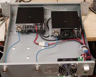
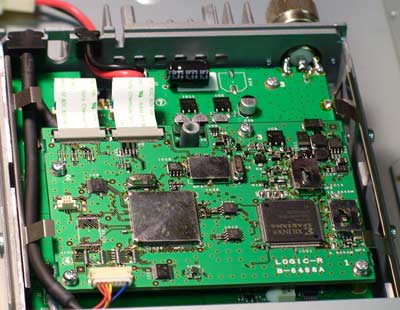
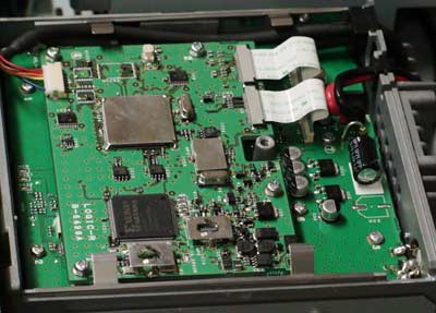
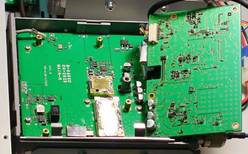
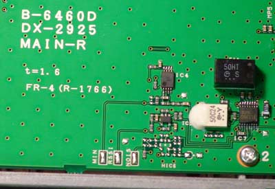
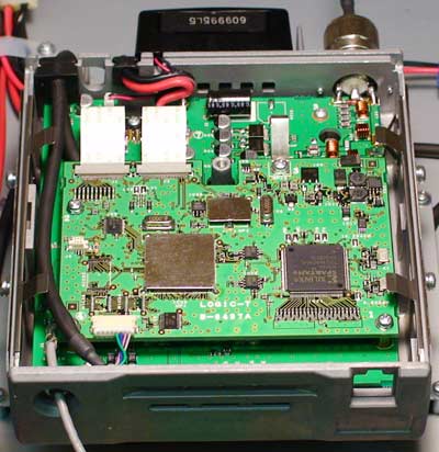
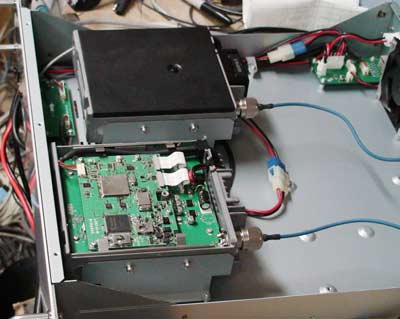
Popping the top on the receiver unit reveals a typical modern transceiver with lots of surface mount components.
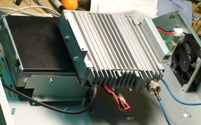
fan.

The receiver heat sink isn't all too beefy... but consider that it's identical to that of the transmitter, just without the small fan.

This is the receiver side.

'NO USER SERVICEABLE PARTS INSIDE' -- at least that's the theory.

Pulling up the top board on the receiver we get a look at the RF board beneath.

Sadly, it's not full of hunky helical resonators like my old trusty Motorola rigs. Hopefully the 'new technology' is better-- but somehow I'm leery.

There's a couple of unused solder pads here with markings that seem interesting.

I wonder if these might be able to provide the elusive 'signal present' indicator or some other useful test point for system alignment and maintenance.

Popping the top on the transmitter yields a similar board arrangement as the receiver. A digital board that sits atop the RF board.

More of the transmitter view.

Yet more of the transmitter. The digital board is in position with it's glorious IC's.

I am rather curious what Icom transceiver they used for the cases here.

With the case back on the transmitter looks a bit less technology laden.


ver 8/08